

| [Home] [Product Search] [Contact] [Terms of Trade] [News] [Newsletter] [Product Sitemap] |
[Cart]
|
Article Groups
Service
| Your position : Flexible Connectors : Busbar support system : Insulators in doubled hexagonal design with threaded steel inserts (9S 20 K zinc coated) |
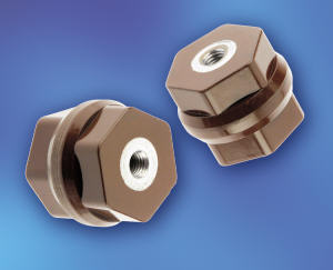 |
Insulators in doubled hexagonal design with threaded steel inserts (9S 20 K zinc coated)Technical data The supports described here are made of a glass-fibre reinforced unsaturated polyester resin. The special characteristic is a doubled hexagonal design. So a hexagonal area is fixed at the top as well as at the bottom of the insulator. Therefore it is quick and easy to install or remove the insulators even in confined spaces. This keeps installation costs down to a minimum. |
||||||||||||||||||||||||||||||||||||||||||||||||||||||||||||||||||||||||||||||||||||||||||||||||||||||||||||||||||||||||||||||||||||||||||||||||||||||||||||||||||||||||||||||||||||||||||||||||||||||||||||||||||||||||||||||||||||||||||||||||||||||||||||||||||||||||||||||||||||||||||||||||||||||||
|
|||||||||||||||||||||||||||||||||||||||||||||||||||||||||||||||||||||||||||||||||||||||||||||||||||||||||||||||||||||||||||||||||||||||||||||||||||||||||||||||||||||||||||||||||||||||||||||||||||||||||||||||||||||||||||||||||||||||||||||||||||||||||||||||||||||||||||||||||||||||||||||||||||||||||
|
F = Rated load limit on upper support edge Z = Tensile force PS = Testing Voltage BWS = Max. AC operating Voltage |
|||||||||||||||||||||||||||||||||||||||||||||||||||||||||||||||||||||||||||||||||||||||||||||||||||||||||||||||||||||||||||||||||||||||||||||||||||||||||||||||||||||||||||||||||||||||||||||||||||||||||||||||||||||||||||||||||||||||||||||||||||||||||||||||||||||||||||||||||||||||||||||||||||||||||
Technical data of the material
|
|||||||||||||||||||||||||||||||||||||||||||||||||||||||||||||||||||||||||||||||||||||||||||||||||||||||||||||||||||||||||||||||||||||||||||||||||||||||||||||||||||||||||||||||||||||||||||||||||||||||||||||||||||||||||||||||||||||||||||||||||||||||||||||||||||||||||||||||||||||||||||||||||||||||||

|
up
-
Print page
-
info@druseidt.de
Copyright © 2000-2019 P. Druseidt Elektrotechnische Spezialfabrik GmbH & Co. KG Neuenkamper Strasse 105 - 42855 Remscheid - Germany Tel.: +49 (2191) 9352-0 - Fax: +49 (2191) 9352-150 |